Overview:
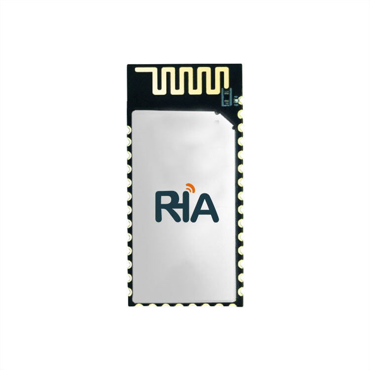
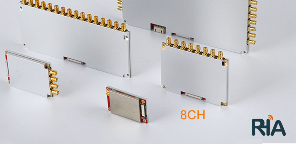
The IoTRHA UHF RFID reader&writer module series includes single/4/8/16/32 channels. These products are designed based on the high-performance Impinj R2000 UHF RFID chip. Utilizing the dynamic Q algorithm from Impinj and our independently developed "Adaptive Dynamic Q Anti-Collision Algorithm V3.0," we have significantly improved multi-tag reading performance. The more tags, the more evident the improvement. The module offers an output power range of 0-33dBm, with a stable reading distance of over 20 meters using a 9dBi circularly polarized antenna and over 30 meters with a 12dBi circularly polarized antenna. The IoTRHA UHF RFID reader&writer module series can be applied to UHF handheld devices, integrated machines, access control channels, smart cabinets, high-quality consumable cabinets, tool cabinets, clothing channels, archive cabinets, and other applications requiring antenna identification and reading.
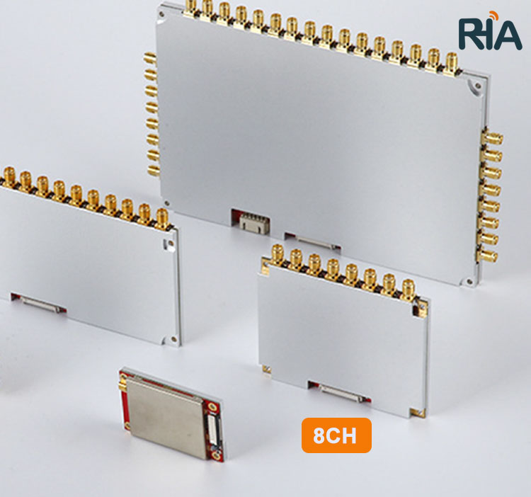
- Eight-Channel reader&writer Module Introduction:
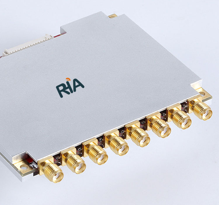
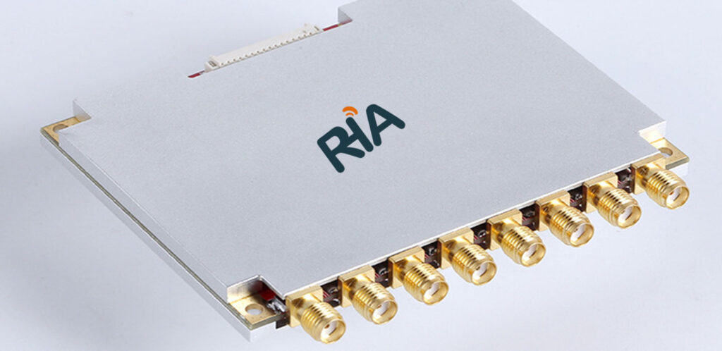
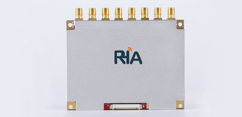
The IoTRHA RHA-500-RC08 UHF RFID Reader/Writer 8-channel module is designed based on the high-performance Impinj R2000 UHF RFID chip. It utilizes Impinj’s dynamic Q algorithm and constructed data models, incorporating our proprietary "Adaptive Dynamic Q Anti-Collision Algorithm V3.0". This algorithm is applied to all our self-developed UHF RFID reader/writer modules. Compared to similar market modules, our modules show significantly improved multi-tag reading performance, especially as the number of tags increases. The module features 8 RF SMA antenna connection ports, allowing simultaneous connection of 8 antennas for real-time inventory. The output power range of the module is 0~33dBm, with a tag reading distance of over 20 meters using a 9dBi circularly polarized antenna and over 30 meters using a 12dBi circularly polarized antenna.
The IoTRHA RHA-500-RC08 UHF RFID Reader/Writer module series can be applied in scenarios requiring antenna-based identification and reading, such as access control channels, smart cabinets, high-quality consumable cabinets, tool cabinets, clothing channels, and file cabinets.
- Key Selling Points:-
- Proprietary core anti-collision algorithm
- Designed based on Impinj R2000’s dynamic Q reading algorithm
- Fully supports EPC Global UHF Class 1 Gen 2 / ISO 18000-6C standard tags
- Operating frequencies: 865MHz~868MHz / 902~928MHz, 860MHz~960MHz (customizable frequency bands)
- Dual CPU design
- Maximum output power up to 33dBm
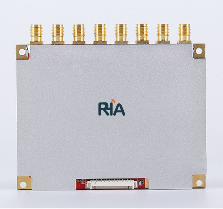
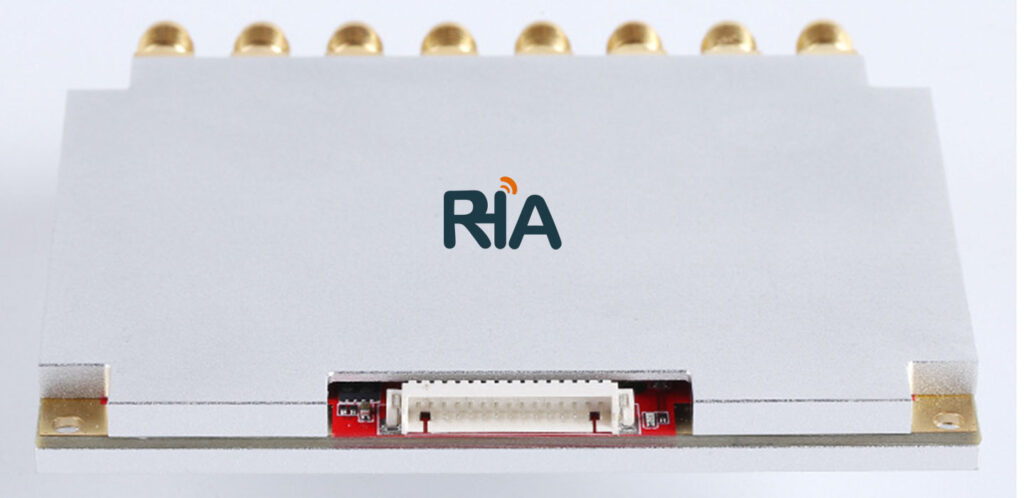
- Equipped with 8 RF SMA antenna connection ports for simultaneous connection of 8 antennas, enabling real-time inventory
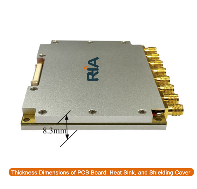
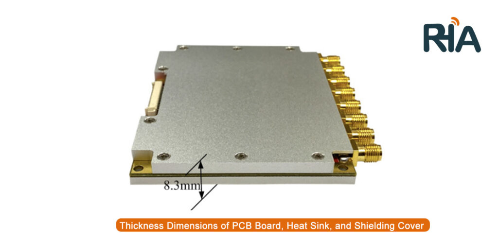
- Excellent heat dissipation design
- Key Performance:
- Core Chip: Utilizes the high-performance Impinj R2000 UHF RFID chip.
- High-Performance Multi-Tag Recognition Algorithm: Based on Impinj’s dynamic Q algorithm and constructed data models, featuring our proprietary "Adaptive Dynamic Q Anti-Collision Algorithm V3.0". This algorithm significantly improves multi-tag reading performance compared to similar market modules, with the difference increasing as the number of tags grows.
- Optimized Algorithm for Few Tags: Designed specifically for applications with few tags, providing ultra-high tag response speed.
- High Output Power Capability: Using a PA chip with stronger amplification output capability, the module’s maximum output power can reach 35dBm. At 33dBm output, the PA remains linear. Higher output power allows for longer reading distances and can activate less sensitive tags in specific applications.
- Dual CPU Architecture: The R2000 chip handles tag polling, while the CPU manages data. Polling tags and sending data are parallel processes, significantly improving overall performance.
- High-Speed 8-Antenna Polling Function: High-speed polling of 8 antenna ports, with a minimum polling time of 50ms per antenna. Each antenna’s polling time can be configured individually.
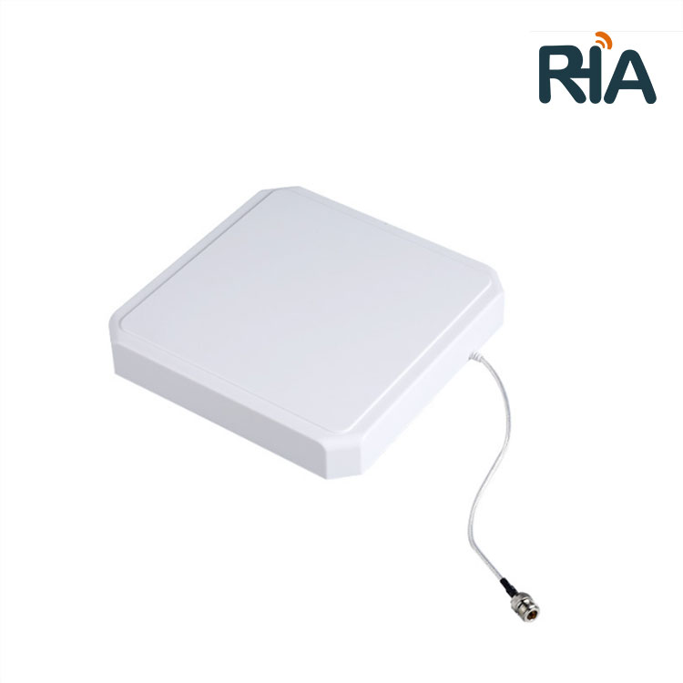
- Exceptional Tag Reading Performance: The module has ultra-low receiving sensitivity and strong amplification output capability. The stable reading distance is over 20 meters with a 9dBi circularly polarized antenna and over 30 meters with a 12dBi circularly polarized antenna.
- Antenna Connection Detection Function: The module integrates an antenna physical connection detection circuit, quickly and accurately detecting the antenna connection status at the module’s ports. The connection status of all module ports can be read with a single command.
- RF Power Amplifier (PA) Protection Function: The module integrates forward and reverse power detection functions. When the module’s RF port starts reading without an antenna connected, it can quickly detect the unconnected antenna state, protecting the PA from damage due to open-circuit output.
- Built-In High-Precision Temperature Sensor: Equipped with a high-precision temperature sensor to accurately monitor the system’s operating temperature in real-time.
- Efficient Heat Dissipation Design: All heating components have thermal structures. The module’s bottom has a large-area heat sink contact. The thermal interface uses high thermal conductivity thermal grease, which does not volatilize at high temperatures.
- High Stability Assurance: Operates continuously without crashing 24/7. Performance is minimally affected by casing, electromagnetic environment, and other external factors. Designed for wide temperature ranges with low temperature drift coefficient. High-quality electronic components ensure stable parameters.
- Simple and Efficient Software and Hardware Interface: Single power supply without the need for an external tantalum capacitor; the module can operate normally with an extremely simple peripheral circuit.
- Application Scenarios:Vehicle management, personnel management, logistics and warehouse management, marathon timing, library management, automated production line management.
- Reader&Writer Module Product Specifications:
| Product Model |
RHA-500-RC08 |
| Operating Voltage |
DC 3.6V - 5V |
| Standby Current |
<50mA (EN pin high level enabled) |
| Sleep Current |
<100uA (EN pin low level enabled) |
| Operating Current |
2.1A @ 5V (33dBm CW Output, 25°C), 1.5A @ 5V (30dBm CW Output, 25°C) |
| Average Current |
1.7A @ 5V (33dBm Output, real-time inventory mode, 25°C) |
| Startup Time |
<50ms |
| Operating Temperature |
-20°C to +70°C |
| Storage Temperature |
-40°C to +85°C |
| Operating Humidity |
<95% (25°C) |
| Air Interface Protocol |
EPC Global UHF Class 1 Gen 2 / ISO 18000-6C |
| Frequency Range |
902MHz - 928MHz (US), 865MHz - 868MHz (EU), 860MHz - 960MHz (customizable) |
| Supported Regions |
US, Canada (FCC); Europe (ETSI EN 302 208); Mainland China, Taiwan, Japan, Korea, Malaysia |
| Output Power Range |
0 - 33dBm |
| Output Power Accuracy |
+/- 1dB |
| Output Power Flatness |
+/- 0.2dB |
| RF Connector |
SMA |
| Receiver Sensitivity |
< -85dBm |
| Inventory Speed |
>700 tags/second |
| Tag RSSI |
Supported |
| Antenna Connection Protection |
Supported |
| Temperature Monitoring |
Supported |
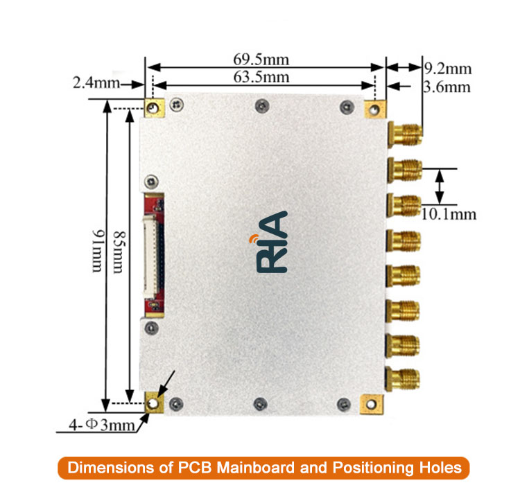
| Antenna Ports |
8 SMA male connectors with internal threads |
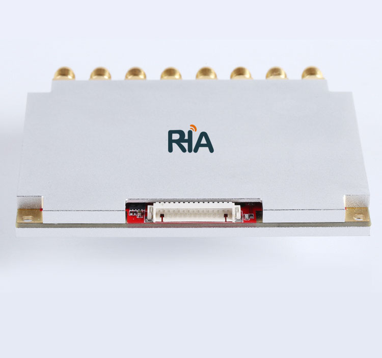
| Communication Interface |
TTL UART |
| GPIO |
2 GPIO inputs, 2 GPIO outputs (3.3V TTL level) |
| Communication Baud Rate |
Standard 115200 bps (options: 38400bps, 460800bps) |
| Cooling Method |
Shielded case and bottom heat sink; additional cooling needed for continuous operation above 30dBm |
- Notes:Avoid full load operation when measured temperature exceeds 60°C.
- Use a heat sink for continuous full-load operation.
- Do not exceed a power supply voltage of 5V to avoid damaging the internal protection circuit.
- Be cautious when setting RF output power above 30dBm due to increased peak current and temperature rise.
- Connector Pin Definitions (1.27mm pitch):
| PIN |
Definition |
Description |
| 1 |
GND |
Ground |
| 2 |
GND |
Ground |
| 3 |
VCC |
Power DC 3.6V~5V |
| 4 |
VCC |
Power DC 3.6V~5V |
| 5 |
GPIO3 |
1st 3.3V TTL level GPIO output |
| 6 |
GPIO4 |
2nd 3.3V TTL level GPIO output |
| 7 |
GPIO1 |
1st 3.3V TTL level GPIO input |
| 8 |
BUZZER |
Buzzer control, requires external driver; optional internal driver |
| 9 |
UART_RXD |
UART RXD (module TTL serial data input) |
| 10 |
UART_TXD |
UART TXD (module TTL serial data output) |
| 11 |
USB_DM |
For internal testing only |
| 12 |
USB_DP |
For internal testing only |
| 13 |
GPIO2 |
2nd 3.3V TTL level GPIO input |
| 14 |
EN |
High level enables the module, low level shuts down the module; default internal pull-up to enable |
| 15 |
485_DIR |
485 data direction control |