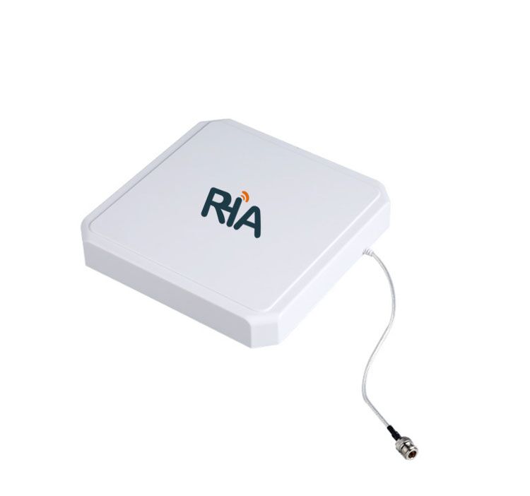
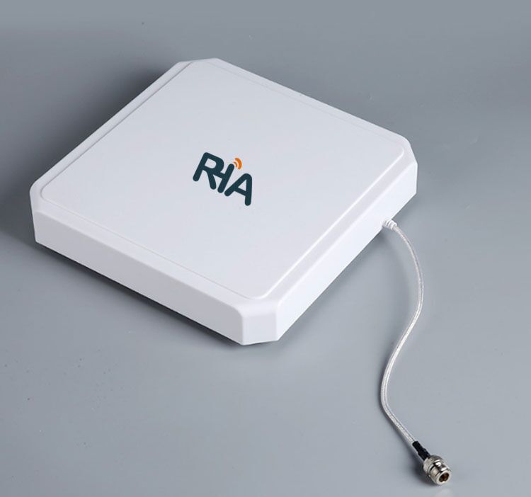
Figure 1: Front view of the 9dBi Circular Polarization Antenna
The 9dBi Circular Polarization Antenna (258) is a versatile far-field antenna suitable for UHF RFID applications. It features high gain and low standing wave ratio, making it ideal for use in UHF RFID applications such as access control, warehousing, logistics, and retail.
Table 1: Technical Specifications of the 9dBi Circular Polarization Antenna (258)
| Product Model | RHA-9W258 |
| Frequency Range (MHz) | 902MHz~928MHz |
| Polarization | Circular |
| Gain (dBi) | >9dBi |
| Axial Ratio (dB) | <3dB |
| H-plane HPBW | 62 degrees |
| E-plane HPBW | 56 degrees |
| Impedance (Ω) | 50Ω |
| Voltage Standing Wave Ratio (VSWR) | ≤1.3:1 |
| Connector Type | N-type external thread female |
| Connector Position | Side feed |
| Product Dimensions (mm) | 258mm×258mm×32mm (excluding back rivet post) |
| Weight | 850g (excluding bracket) |
| Material | Engineering plastic ABS + aluminum |
| Color | Off-white |
| Protection Level | IP65 |
| Installation Method | Pole mount (maximum pole diameter 50mm) |
| Operating Temperature (°C) | -40°C ~+85°C |
(1) Gain vs. Frequency Curve

Figure 2: Gain vs. Frequency Curve
(2) Axial Ratio vs. Frequency Curve
Figure 3: Axial Ratio vs. Frequency Curve
(3) H-plane 2D Radiation Pattern (Horizontal Beam Pattern)
Figure 4: H-plane 2D Radiation Pattern
(4) E-plane 2D Radiation Pattern (Vertical Beam Pattern)
Figure 5: E-plane 2D Radiation Pattern
(5) Return Loss S11 vs. Frequency Curve
Figure 6: Return Loss S11 vs. Frequency Curve
(6) Voltage Standing Wave Ratio (VSWR) vs. Frequency Curve
Figure 7: Voltage Standing Wave Ratio (VSWR) vs. Frequency Curve
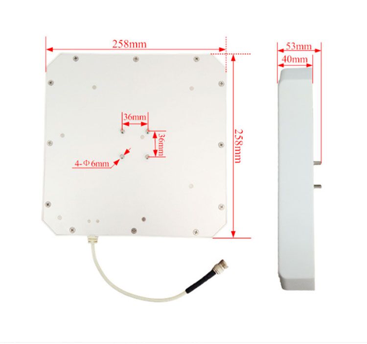
Figure 8: Length, width, thickness, and back rivet post position dimensions of the 258 antenna