Overview:
The IoTRHA UHF RFID reader&writer module series includes single/4/8/16/32 channels. These products are designed based on the high-performance Impinj R2000 UHF RFID chip. Utilizing the dynamic Q algorithm from Impinj and our independently developed "Adaptive Dynamic Q Anti-Collision Algorithm V3.0," we have significantly improved multi-tag reading performance. The more tags, the more evident the improvement. The module offers an output power range of 0-33dBm, with a stable reading distance of over 20 meters using a 9dBi circularly polarized antenna and over 30 meters with a 12dBi circularly polarized antenna. The IoTRHA UHF RFID reader&writer module series can be applied to UHF handheld devices, integrated machines, access control channels, smart cabinets, high-quality consumable cabinets, tool cabinets, clothing channels, archive cabinets, and other applications requiring antenna identification and reading.
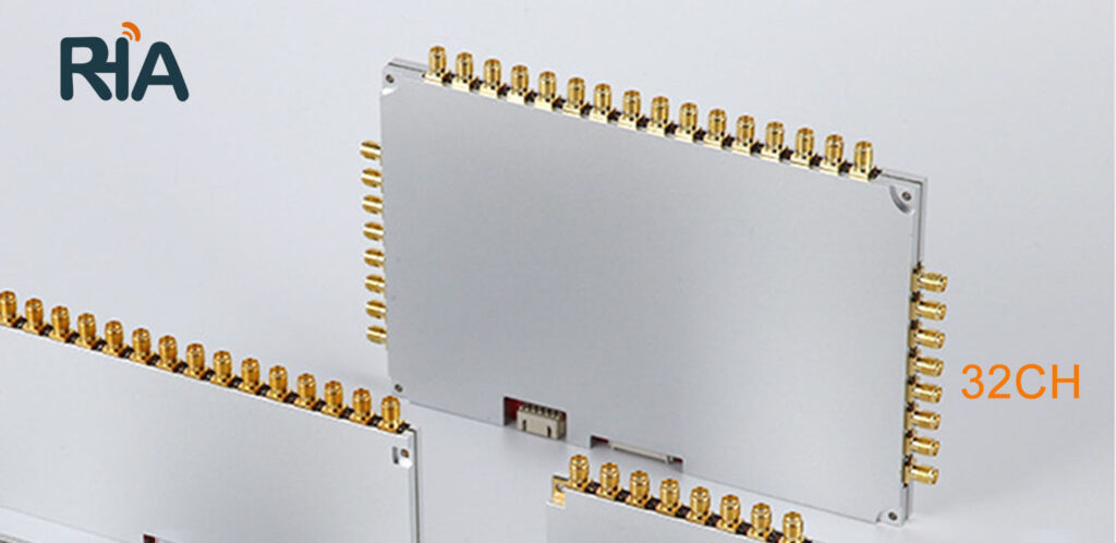
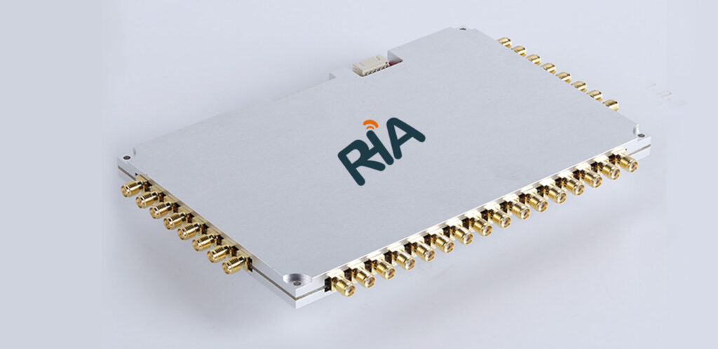
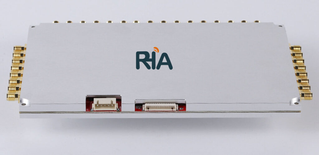
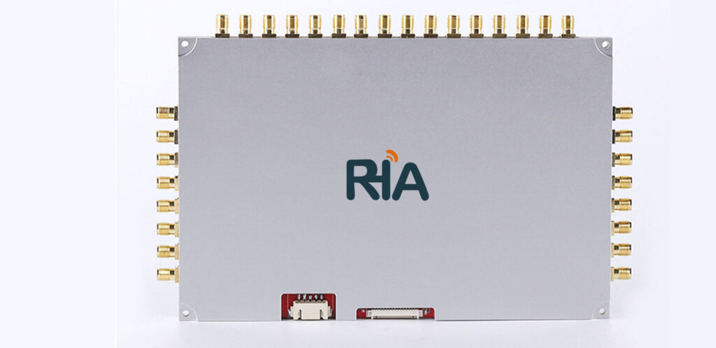
The IoTRHA RHA-500-RC032 is a UHF RFID reader & writer module designed with the high-performance UHF dedicated RF chip, Impinj R2000. Utilizing the dynamic Q algorithm and data model constructed by the American company Impinj, it incorporates our proprietary “Adaptive Dynamic Q Anti-collision Algorithm V3.0”. This algorithm is applied to all our UHF RFID reader & writer modules, significantly improving multi-tag reading performance compared to similar market modules. The module supports 32 RF SMA antenna ports, enabling the connection of up to 32 antennas for real-time inventory. The module's output power ranges from 0 to 33dBm, with a long reading distance: stable identification at over 20 meters with a 9dBi circularly polarized antenna and over 30 meters with a 12dBi circularly polarized antenna.
The IoTRHA RHA-500-RC032 UHF RFID reader & writer module series is suitable for various applications requiring antenna identification and reading, such as access control channels, smart cabinets, high-quality consumable cabinets, tool cabinets, apparel channel machines, and file cabinets.
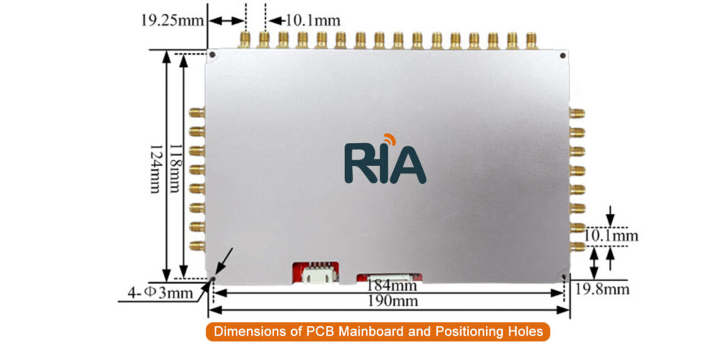
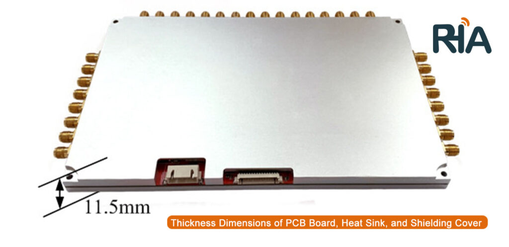
| Product Model | RHA-500-RC032 |
| Operating Voltage | DC 3.6V - 5V |
| Standby Current | <50mA (EN pin high level enabled) |
| Sleep Current | <100uA (EN pin low level enabled) |
| Operating Current | 2.1A @ 5V (33dBm CW Output, 25°C), 1.5A @ 5V (30dBm CW Output, 25°C) |
| Average Current | 1.7A @ 5V (33dBm Output, real-time inventory mode, 25°C) |
| Startup Time | <50ms |
| Operating Temperature | -20°C to +70°C |
| Storage Temperature | -40°C to +85°C |
| Operating Humidity | <95% (25°C) |
| Air Interface Protocol | EPC Global UHF Class 1 Gen 2 / ISO 18000-6C |
| Frequency Range | 902MHz - 928MHz (US), 865MHz - 868MHz (EU), 860MHz - 960MHz (customizable) |
| Supported Regions | US, Canada (FCC); Europe (ETSI EN 302 208); Mainland China, Taiwan, Japan, Korea, Malaysia |
| Output Power Range | 0 - 33dBm |
| Output Power Accuracy | +/- 1dB |
| Output Power Flatness | +/- 0.2dB |
| RF Connector | SMA |
| Receiver Sensitivity | < -85dBm |
| Inventory Speed | >700 tags/second |
| Tag RSSI | Supported |
| Antenna Connection Protection | Supported |
| Temperature Monitoring | Supported |
| Antenna Ports | 32 SMA male connectors with internal threads |
| Communication Interface | TTL UART |
| GPIO | 2 GPIO inputs, 2 GPIO outputs (3.3V TTL level) |
| Communication Baud Rate | Standard 115200 bps (options: 38400bps, 460800bps) |
| Cooling Method | Shielded case and bottom heat sink; additional cooling needed for continuous operation above 30dBm |
| PIN | Definition | Description |
| 1 | GND | Ground |
| 2 | GND | Ground |
| 3 | VCC | Power DC 3.6V~5V |
| 4 | VCC | Power DC 3.6V~5V |
| 5 | GPIO3 | 1st 3.3V TTL level GPIO output |
| 6 | GPIO4 | 2nd 3.3V TTL level GPIO output |
| 7 | GPIO1 | 1st 3.3V TTL level GPIO input |
| 8 | BUZZER | Buzzer control, requires external driver; optional internal driver |
| 9 | UART_RXD | UART RXD (module TTL serial data input) |
| 10 | UART_TXD | UART TXD (module TTL serial data output) |
| 11 | USB_DM | For internal testing only |
| 12 | USB_DP | For internal testing only |
| 13 | GPIO2 | 2nd 3.3V TTL level GPIO input |
| 14 | EN | High level enables the module, low level shuts down the module; default internal pull-up to enable |
| 15 | 485_DIR | 485 data direction control |
| PIN | Definition | Description |
| 1 | VCC | Power DC 12V |
| 2 | GND | Ground |
| 3 | GND | Ground |
| 4 | RS_232 RXD | Module RS232 serial data input |
| 5 | RS_232 TXD | Module RS232 serial data output |
